|
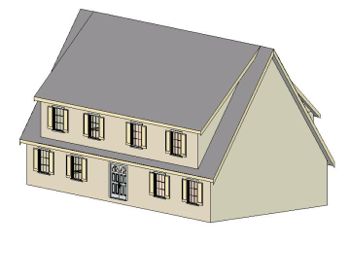
"Providence House" Inspiration for this roof design came from the T.V. Show Providence, which airs on NBC. |
I first saw this roof design on the T.V. show "Providence" and wondered if I could carry out the design using 3DHA. Sure enough, it turned out quite easy to do. This is how this lesson came to get it's name.You might have already noticed this roof design in the lesson about Views. It seemed like a very good design to show off the different view capabilities that 3DHA possesses. The two separate roof pitches help you appreciate the Cross Section view found in 3DHA, but not in many other low cost modeling programs. |
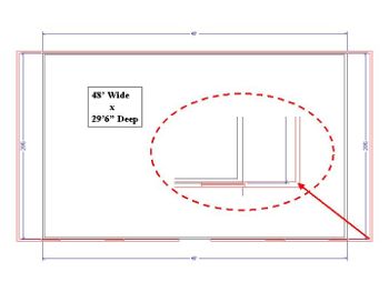
| We'll start by making a 1st floor that is 56' wide by 30'
deep. Add some windows and a door in the front of the house (bottom).
Make one window and then modify it to look the way you want it to by
opening its dialog box (double-click it) and changing its properties.
Once the window looks like you want, use it to make copies for the rest
of the front windows. Select the window, then click its Copy Tool, then
click where the next window goes. Repeat this until you have the number
of windows you desire.
Next, we will want to set the Roof Section at Wall properties of each of the 1st floor walls before moving on to the 2nd floor. |
|
|
|
From the Main Toolbar, choose the Roof Tool, which should activate the Roof Toolbar and make the Roof Section at Wall tool active. Now you can simple single click on a wall to open its Roof Section at Wall dialog box. For each of the two side walls, place a check mark in the checkbox next to Full Gable Wall. For the Front and Back walls, change the Pitch from 6 [D] in 12 to 18 3/4 in 12. If you made your 1st floor a different depth than we did (30'), then the roof pitch will need to be adjusted. But do that later. |
| Now let's build the 2nd floor. From the Main Menu, select Window, then Show Floors and the Show Floors dialog box should open. Right now you only have a 1st floor and an attic. (which 3DHA is assuming) Click the Build button under attic and the New Working Plan dialog box will open. Leave the Option Button for "Derive new 2nd floor plan from 1st floor plan" selected and just click OK. That will take you back to the previous dialog box. Click OK again and a 2nd floor will be created. At this point 3DHA not only created a 2nd floor, but it also switched you to that floor. So that is where you are now working. We want to alter the size of this floor as it relates to the 1st floor so we want to turn on the Reference Toggle. To do that, choose Window from the Main Menu, then Reference Toggle. |
|
|
|
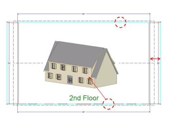
The 1st floor should become visible as red lines. Where the first floor lines up with the 2nd, the combination of the red (1st/reference floor) and the black (2nd/working floor) creates a light blue line. But if you select a wall you will be selecting the 2nd floor wall because it is the Working floor. Move both the Front Wall and the Back wall toward the middle of the model by about 3", leaving a 2nd floor depth of 29'6". I will explain why later. Next, move both of the side walls toward the middle by 4', leaving the 2nd floor width to be 48' (56'-4'-4'). |
|
Now we need to set the Roof Sections at Wall for the 2nd floor. So do the same as you did for the 1st floor. Choose the Roof Tool -> Roof Section at Wall tool. Click the side walls and choose Full Gable Wall. Click the Front and Back walls and change the Pitches to 12 in 12 rather than 18 3/4 in 12. This is different than the 1st floor in order to get the roof from the 1st floor to end at the same height as the roof on the 2nd floor. The picture that follows shows the changes that needs to be made. |
|
|
|
Before building the roof, add some windows to the 2nd
floor. You can either add a new window as you did on the 1st floor or go
to the 1st floor, select a window, click the Copy tool, return to the
2nd floor, and paste the window into the front wall of the 2nd floor.
Then make more copies to finish the 2nd floor.
Now just build the roof. Choose the Roof Tool from the Main Toolbar, which activates the Roof Toolbar. Click the middle tool (Build Roof) and the build Roof dialog box opens. Change the Roof Overhang (normal) to 6 due to the steep roof angles we are using. Click OK and your roof will build. You should see the dotted lines representing your roof in plan view. |
| Select the View Tool from the Main Toolbar and the View Toolbar will appear. Click on the Full Overview tool (last tool on the right) and you should see something close to the following picture. If your two roofs do not line up at the top as shown in this picture, then you will have to increase or decrease the Roof Pitch of either the 1st floor or 2nd floor until they align. Unless you are looking to have the roof ridges offset. |
|
|
|
Earlier I said I would explain why you moved the exterior
walls of the second floor in toward the middle of the model while you
were building the 2nd floor. It was to create the roof overhang (eaves)
where the 2nd floor covers the 1st. (as shown in the picture above) If
you want to remove that overhang (as shown in the picture to the left),
just move your 2nd floor Front and Back walls directly over the 1st
floor walls and then re-build your roof. The eaves in this area should
disappear.
You moved the end walls on the 2nd floor in 4' to create the narrow roof sections on the left and right ends. |